Introduction
We are back with Round 2 of the Off-By-One conference — where bits meet breadboards and bugs are celebrated! 🐛⚡
If you are into hardware and IoT security, you’ll know one thing’s for sure: the STAR Labs SG badge is not your average conference bling bling. This year’s badge isn’t just a collector’s item — it’s a playground for the curious, packed with new challenges inspired by months’s worth of research and hackery. And yes, the CTF is back, with even more nerdy goodness.
But before we plug into what’s new, let’s do a quick flashback to last year’s Octopus badge. That little guy had personality — literally. With two round screens as eyes, attendees had a blast giving their octo-buddy a range of emotions. Some even got creative and hacked in their own custom graphics. Total respect to those two Canadians.
Unlike the usual plug-it-in, solve-a-riddle USB badges, we are constantly trying to add learning value to it. We turned the badge into a hands-on intro to hardware-hacking — think I2C, SPI, and MicroPython quirks. Oh, and remember the mini voltage glitching challenge? Yup, all on the same board. We hope it sparked a few “Aha!” moments for those digging into hardware for the first time.
Fast forward to 2025: we’ve cranked the nerd 🤓 dial all the way up — channeling a bit of “Back to the Future” energy (which, by the way, is also one of this year’s T-shirt designs). And yes, we’ve officially gone full throttle: the lanyard is now part of the challenge. You heard that right — lanyard hacking is a thing now.
To give you the inside scoop, we’ve got Sarah and Manzel on deck to walk you through the Behind the Scenes — from design choices to the delightful chaos that comes with building hackable hardware. Buckle up. This one’s gonna be a fun ride.
Lanyard Challenge
Hi, my name is Sarah, and I’m the creative lead here at STAR Labs :)
I was tasked with creating a lanyard challenge for this year’s Off By One 2025, and to be honest, I had no idea how to go about it. Yes, I’ve heard about encryptions and ciphers, but I’d never actually used them to build a puzzle before.
We wanted a puzzle that required multiple lanyards to be matched up and arranged in the correct order to reveal the key/flag.
There were four lanyard colors in total: attendees, speakers, crew, and sponsors. The tricky part? We didn’t make an equal number of each! Sponsors, who had green lanyards, had the fewest available—and that’s exactly where the final puzzle was hidden.
Only by lining up the lanyards in the right sequence would the correct code appear. This is an earlier version I was initially toying with which features MD5 hash and the nyctograph cipher. At first I wanted to cut up the cipher and have them distributed across the lanyards so people would have to match them up accordingly to get the full text.
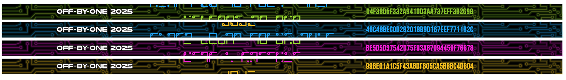
I reached out to several colleagues, including Jacob, for ideas and eventually settled on using ROT13 instead of the MD5 hash. We also scrapped the plan to chop the cipher up into pieces.
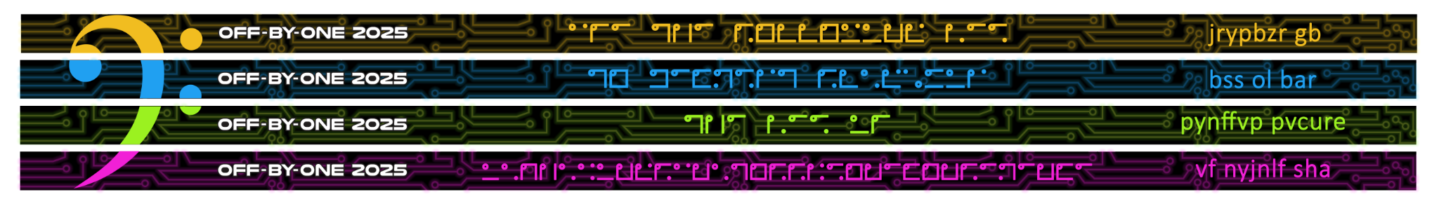
We did make sure to field test the design in the office to make sure it was solvable but it did take a little while for the staff to understand what they were looking at; a good number of them thought the ciphers were just part of the design. A bass clef was subtly hidden in the lanyards to help indicate the correct order they were supposed to be in.
It was hilarious (and satisfying) watching students scramble around once they realized the “random” symbols on the lanyards actually meant something. Once they had the flag/key, they could use it to unlock the final key phrase hidden inside this year’s badge.
Fun Facts: There was a clue buried in the badge—an Alice in Wonderland illustration of the White Rabbit with the words “Follow the White Rabbit.” This was both a hint and an Easter egg, since the nyctograph cipher was invented by Lewis Carroll himself!

Badge Design
Now let us discuss and take a look at our brand new badge design as well! Our new design is a robot character incorporating a retro-themed user interface.
![]()
In terms of hardware components, we explored LCDs with relatively high-resolution graphics and display update rate. Having this, we were able to include GIF playback support, which allowed us to bring in cute animated facial expressions for our little robot friend.
![]()
As a nice touch, we also added customized name-cards for our speakers.
![]()
Now let me pass my time to Manzel, the electronics wizard who created the circuitry and CTF challenges.
Hardware Circuit
Hi I am Manzel and I am the Hardware Engineer at STAR Labs SG.
Thinking of a new hardware circuit is always interesting as we aim to incorporate new features that we have previously looked at during the course of our research.
A key feedback from last year is that the badge was too heavy, therefore we decided to reduce to 2 AAA batteries. Effectively cutting the weight by 25%. However, because the battery capacity has been reduced, we changed to the newer ESP32-C3 which is slightly more battery-efficient than the ESP32-S3. It also has a single RISC-V core which is also a good platform to learn about RISC-V architecture.
Internally, we have done 3 prototypes and here is how they look:
![]()
Our first blue prototype was an LED bit matrix. It received good feedback because it captured the retro theme of the conference well. However, we later discovered a high failure rate as the small LEDs are fragile.
Doing a DIY fix isn’t easy with the plastic LEDs. This means desoldering repair work may risk damaging/overheating the surrounding LEDs as well.
Therefore we decided to pivot to LCD displays. For the green prototypes, we accounted for two different displays.
While the larger rectangular display had better proportions, it has a poor pixel density and contrast ratio, making our artwork look too blurry.
The smaller LCD has a higher pixel density and refresh rate. With little time left to the conference, we decided to settle on the smaller LCD, as we could present GIF animations which is something not commonly done in other conference badges.
Overall this is the timeline
- 23 Jan: Manufacturing of Blue Prototype Manufacturing
- 6 Feb: Feedback & Testing of Blue Prototype
- 5 Mar: Manufacturing of Green Prototype
- 17 Mar Feedback & Testing of Green Prototypes
- 7 Apr: Mass Manufacturing of Final Badges
- 25 Apr: Programming of CTF Challenges
- 8 May: Conference Day!
Typically, each prototype takes about 2 weeks to manufacture, with testing of hardware and firmware about 3 weeks.
![]()
Hardware CTF Challenges
For the challenge this year, we decided to focus on hardware peripherals like the bootloader and internal registers. In addition, we will take a brief look at retro wireless communication.
![]()
1. Welcome Flag (Category: Welcome)
Challenge: Welcome to hardware hacking! Here is a flag:

The first flag is a sanity check which aligns with the retro-theme of the conference. The history of the barcode can be traced back to the 1950s before it became adopted quickly for inventory tracking.
Take note that the black borders of the screen interfered with the scanning on some phone apps. You may take a close up photo or crop away the screen borders before scanning.
![]()
Scan the barcode to get the flag.
Flag: {WelcomeToObo2025}
2. Retro Music (Category: Communication)
Challenge: My boss asked me to compose some music. I used AI to generate it for me instead.
In this challenge, a sequence of tones are played. Listening carefully we identify 2 distinct tones. Therefore, we can immediately eliminate Morse code because Morse code consists of a single tone of varying lengths (ie. long or short beeps).
Instead, we deduce that the 2 distinct tones can represent binary. This is a simple example of Frequency-shift keying (FSK). In particular, it is Binary FSK (BFSK) which used to represent binary 0 and 1 with only two distinct sets of [audio] frequencies.
FSK was especially used in early radio communication like Pagers and Dial-up modems.
We can identify them by using an audio spectrum analyser. A mobile app – for example, Spectroid – can be used if one does not have access to a computer.
From the frequency spectrum plot, we first identify the 2 peak frequencies with the largest magnitude. In this case, we see pulses of 2730Hz and 3141Hz as the music is being played. We can zoom into this range and ignore the noise from other frequencies.
![]()
By inspection, the “0” is chosen for the low frequency tone, while a “1” is the higher frequency tone. From here, it can be converted into the ASCII representation of the flag.
![]()
Flag: {FSK_On_A_Budget}
Activities Booth (Category: Communication)
Challenge: I found a remote control which appears to do much more. I managed to capture the signal using a Flipper Zero.
Filetype: IR signals file
Version: 1
#
name: button_name
type: raw
frequency: 38000
duty_cycle: 0.5
data: 1040 104 208 104 416 104 520 104 104 104 104 104 104 104 104 104 520 104 104 520 104 104 520 208 104 208 104 104 104 104 520 312 104 104 104 104 104 104 520 104 520 104 104 104 520 104 416 208 104 104 520 208 208 104 312 104 520 104 104 104 104 208 208 104 520 208 104 208 312 104 520 104 520 104 104 104 520 104 104 208 104 208 104 104 520 208 312 104 208 104 520 208 208 208 208 104 520 208 104 208 312 104 520 104 104 416 208 104 520 208 104 208 312 104 520 104 104 104 104 208 208 104 520 312 104 208 208 104 520 104 520 104 104 104 520 104 624 208 520 104 104 416 104 208 520 104 624 208 520 104 104 416 104 208 520 104 104 104 520 104
# end of file
This challenge involves an Infrared (IR) signal dump. IR communication is usually used in remote controls to send commands to other devices like TVs or Soundbars. There are many tools that can be used to copy these IR signals and replay them.
From the docs, we understand that the Flipper Zero saves the demodulated signal into a .ir file:
Flipper Zero captures and demodulates IR signals with a carrier frequency of 38 kHz with its built-in IR receiver. For remotes with known protocols, Flipper Zero automatically decodes IR signals. If the protocol of the remote is unknown, Flipper Zero will record the signal in RAW format.
We also see that the .ir file format presents the raw data in terms of microseconds. This is the timing of logic levels changes as it alternates between digital logic 1 and 0. Refer to Infrared Flipper File Formats.
Therefore, from the data provided data: 1040 104 208 ..., the logic capture will look something like this:
![]()
We can convert it into a bitstream first.
ir_data = "1040 104 208 104 ... 520 104"
for i, num in enumerate(ir_data.split(" ")):
    value = 1 if ((i % 2) == 0) else 0
    for x in range(int(num)):
        print(f"{value}")
However this bitstream cannot be directly interpreted as data yet. Communication protocols may include additional bits such as preamble bits, checksum, or bits to indicate start and end of a frame. Therefore parsing it manually will be tedious.
Typically, an engineer will use a logic analyzer program like PulseView to identify and decode an unknown signal. This is an open-source program and it supports the decoding of numerous different protocols.
After importing the data, we can narrow down to only asynchronous protocols, since there is only 1 signal/channel provided. Likewise, we determine the baud rate by taking the shortest pulse of 104us which gives us approximately 9600 Hz.
Finally, we may import it as a .csv file and the signal can then be decoded as UART with baud rate of 9600.
![]()
Zooming in, one can also observe how the start bits and stop bits are detected.
![]()
Flag: {UART_Over_Infrared_?!?!}
Diagnostic Mode (Category: Bootloader)
Challenge: Oops! The engineering team left the diagnostic test mode in the production firmware. There may be an easter egg.
Diagnostic modes or internal menus are often found in electronic devices to check for hardware and software issues. For example, you may hold down certain key combinations while turning the device on in order to enter the recovery mode of a smartphone or diagnostic mode of a laptop.
It is useful to know that the bootloader of the ESP32-C3 microcontroller supports a test mode. The test app can be triggered by a button press during bootup. Refer to the note for CONFIG_BOOTLOADER_NUM_PIN_APP_TEST
If we restart the badge with the Down button pressed, it boots into a test mode. Complete the diagnostics procedure to see the flag on the screen.
![]()
Flag: {Disable_Unnecessary_Diagnostics_Or_Engineering_Test_Modes_If_Possible}
Hidden Partition (Category: Bootloader)
Challenge: I didn’t know that IoT microcontrollers can have multiple partitions.
To solve this, we need to understand that the bootloader supports partitions. There exists a partition table. In the ESP32-C3, the partition table is located in the flash memory at 0x8000 by default. https://docs.espressif.com/projects/esp-idf/en/stable/esp32c3/api-guides/partition-tables.html
We can use esptool and gen_esp32part.py to dump the partition table from this offset of the flash memory.
$ esptool.py read_flash 0x8000 0xc00 binary_partitions.bin
$ python3 gen_esp32part.py binary_partitions.bin input_partitions.csv
Parsing binary partition input...
Verifying table...
The partition table looks like this
$ cat input_partitions.csv
# Name,           Type,   SubType,    Offset,     Size
flag_xorkey,      data,   undefined,  0x9000,     4K
nvs,              data,   nvs,        0xa000,     8K
circuitpython,    app,    ota_0,      0x10000,    1536K
ctf,              app,    ota_1,      0x190000,   760K
user_fs,          data,   fat,        0x24e000,   1416K
diagnostics,      app,    test,       0x3b0000,   316K
flag_enc,         data,   undefined,  0x3ff000,   4K
Here we notice the partition names flag_xorkey located at offset 0x9000 and flag_enc at offset 0x3ff000.
Here is how to dump out the contents using esptool
$ esptool.py read_flash 0x9000 0x1000 flag_xorkey.bin
$ esptool.py read_flash 0x3ff000 0x1000 flag_enc.bin
Finally, we can xor the contents together to get the flag.
$ pip3 install xortool
$ xortool-xor -f flag_enc.bin -h "$(xxd -p flag_xorkey.bin)"
The ESP partition table divides flash memory into segments, such as bootloader, application, ota updates and data storage. We can embed multiple apps onto a single flash, encrypt partitions and hide some flags {IoT_Device_Bootloader_Partition_Scheme}.
Flag: {IoT_Device_Bootloader_Partition_Scheme}
HMAC Oracle (Category: Bootloader)
Challenge: You found someone’s hardware token. Apparently it can generate HMACs, can you find the key? Access via USB serial. Hint: HMAC peripheral on ESP32-C3.
Firstly, this is a hardware challenge and not a crypto challenge. We should first understand how the HMAC hardware peripheral works.
The HMAC (Hash-based Message Authentication Code) module provides hardware acceleration for SHA256-HMAC generation using a key burned into an eFuse block. HMACs work with pre-shared secret keys and provide authenticity and integrity to a message.
There are some references to the eFuse block. It is a one-time programmable area and usually used for permanent configurations in an IoT system. In this case, it is used to store a key for use by the HMAC peripheral only.
A configuration mistake here is that key protection was not enabled. The HMAC key which was written into the eFuse could be read out using the programming tool espefuse.py.
    $ espefuse.py dump --port /dev/ttyACM0
        espefuse.py v4.6.2
        Connecting...
        Detecting chip type... ESP32-C3
        BLOCK0          (       ) [0 ] read_regs: 00000100 00000000 08000000 00000000 80000000 00000000
        MAC_SPI_8M_0    (BLOCK1 ) [1 ] read_regs: b0df1be0 000034cd 00000000 03100000 70f0e330 00070ab0
        BLOCK_SYS_DATA  (BLOCK2 ) [2 ] read_regs: 17b68a5c c97867c1 f1c688f4 6a4548b3 99346b61 1aea3e8a d6538926 00000009
        BLOCK_USR_DATA  (BLOCK3 ) [3 ] read_regs: 00000000 00000000 00000000 00000000 00000000 00000000 00000000 00000000
        BLOCK_KEY0      (BLOCK4 ) [4 ] read_regs: 726f467b 5f746f67 5f79654b 64616552 5f74756f 746f7250 69746365 207d6e6f
        BLOCK_KEY1      (BLOCK5 ) [5 ] read_regs: 00000000 00000000 00000000 00000000 00000000 00000000 00000000 00000000
        BLOCK_KEY2      (BLOCK6 ) [6 ] read_regs: 00000000 00000000 00000000 00000000 00000000 00000000 00000000 00000000
        BLOCK_KEY3      (BLOCK7 ) [7 ] read_regs: 00000000 00000000 00000000 00000000 00000000 00000000 00000000 00000000
        BLOCK_KEY4      (BLOCK8 ) [8 ] read_regs: 00000000 00000000 00000000 00000000 00000000 00000000 00000000 00000000
        BLOCK_KEY5      (BLOCK9 ) [9 ] read_regs: 00000000 00000000 00000000 00000000 00000000 00000000 00000000 00000000
        BLOCK_SYS_DATA2 (BLOCK10) [10] read_regs: 00000000 00000000 00000000 00000000 00000000 00000000 00000000 00000000

        BLOCK0          (       ) [0 ] err__regs: 00000000 00000000 00000000 00000000 00000000 00000000
        EFUSE_RD_RS_ERR0_REG        0x00000000
        EFUSE_RD_RS_ERR1_REG        0x00000000

        === Run "dump" command ===
Here we see the flag in BLOCK_KEY0 (BLOCK 4)
Flag: {Forgot_Key_Readout_Protection}
Additional note: When setting up any one-time-programmable (OTP) memory, ensure readout protection by enabling all key security features once programming is finalized. Additionally, we should activate secure boot to prevent end-users from executing arbitrary code, which could otherwise be used to exfiltrate keys via hardware functions. The challenge of bypassing such read-out protection is a significant research area. A notable and recent example is the RP2350 Hacking Challenge, where the end goal is to break the OTP protection.
Conclusion
![]() A huge thank you to all participants for making this conference a success. We hope you enjoyed our mashup of challenges in the lanyard and tech badge. Your feedback is welcome as we look ahead to create new ideas for next year’s iteration!
A huge thank you to all participants for making this conference a success. We hope you enjoyed our mashup of challenges in the lanyard and tech badge. Your feedback is welcome as we look ahead to create new ideas for next year’s iteration!